Support for the GD32VF103C-START board. More...
Detailed Description
Support for the GD32VF103C-START board.
Overview
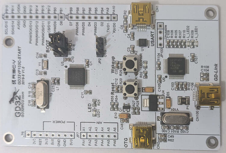
The GD32VF103C-START development board is an official starter kit by GigaDevice for the GD32VF103CBT6 MCU, despite the lack of official documentation. It featrures:
- GD32VF103CBT6 RISC-V MCU @108MHz
- On-Board GD-Link Programmer/Debugger (middle mini-USB connector)
- USB-OTG (left mini-USB connector)
- Integrated USB to UART bridge (right mini-USB connector)
- 1 user LED
- 1 user Button
- 1 reset button
- Arduino UNO compatible pin headers (except ISP header)
- Warning
- The analog pins are labeled A1 - A6 rather than A0 - A5, as would be the correct Arduino naming. The Arduino pin mapping uses the correct Arduino naming, so that apps written for other boards expecting Arduino UNO compatible shields remain compatible.
Hardware
| MCU | GD32VF103CBT6 | Supported |
|---|---|---|
| Family | RISC-V with ECLIC | |
| Vendor | GigaDevice | |
| RAM | 32 KiB | |
| Flash | 128 KiB | |
| Frequency | 108 MHz | |
| Power Modes | 3 (Sleep, Deep Sleep, Standby) | yes |
| GPIOs | 37 | yes |
| Timers | 5 x 16-bit timer | yes |
| RTC | 1 x 32-bit counter, 20-bit prescaler | yes |
| WDT | 2 x 12-bit counter, 3-bit prescaler | yes |
| ADC | 2 x 12-bit units, 16 channels @ 1 Msps | yes |
| DAC | 2 x 12-bit channel | yes |
| UART | - | yes |
| USART | 3 | yes |
| SPI | 3 | yes |
| I2C | 2 x Fast Mode 400 kHz | yes |
| I2S | 2 | no |
| CAN | 2 x CAN 2.0B with up to 1 Mbps | no |
| PWM | 6 Channels | yes |
| USB | 1 x USB FS OTG (+ GD-Link + UART bridge) | yes |
| Vcc | 3.0V - 3.6V | |
| Datasheet | Datasheet | |
| User Manual | User Manual | |
| Board Manual | Board Manual |
Flashing
- Warning
- Flashing seems to fail with some Arduino UNO compatible boards attached. Remove them and try again.
By default, flashing is done via OpenOCD using the GD-Link programmer/debugger using:
It is also possible to flash via DFU-Util:
- Connect a mini USB cable to the USB connector labeled OTG.
- Power the board (e.g. by connecting a second mini USB cable to the GD-Link programmer/debugger, even though we won't use it)
- Enter the DFU bootloader by placing the jumper on JP4 (below BOOT) in position H. Press the reset button afterwards.
- Run
make BOARD=gd32vf103c-start PROGRAMMER=dfu-util -C path/to/app flash - Restore the JP4 jumper to position L. Afterwards press the reset button again
Connecting to the Serial Output
By default RIOT's uses UART for stdio. To access that, connect a mini USB cable to the connector labeled "USART". In addition a jumper needs to be placed on JP2 in the "Usart" position; otherwise RIOT's TXD is not connected to the RXD of the integrated USB UART bridge. Afterwards just run:
Alternatively, stdio_cdc_acm can be used. In this case the mini USB cable needs to be connected to the USB connector labeled OTG.
- Note
- It is safe to keep the jumper at JP2 in "Usart" position or even remove the jumper with RIOT. PA9 is still used as UART/TXD and VBUS sensing is disabled anyway.
Files | |
| file | arduino_iomap.h |
| Mapping from MCU pins to Arduino pins. | |
| file | board.h |
| Board specific definitions for the GD32VF103C-START board. | |
| file | gpio_params.h |
| Configuration of SAUL mapped GPIO pins. | |
| file | periph_conf.h |
| Board specific definitions for the GD32VF103C-START board. | |
