Support for the Seeed Studio Xiao ESP32-C6 board. More...
Detailed Description
Support for the Seeed Studio Xiao ESP32-C6 board.
Seeed Studio Xiao ESP32C6
Overview
Seeed Studio Xiao ESP32C6 is a small board based on the Espressif ESP32-C6 SoC, featuring two 32-bit RISC-V processors: a high-performance core running at up to 160 MHz and a low-power core clocked up to 20 MHz.
- Wi-Fi 6 2.4 GHz
- Bluetooth 5 (LE)
- IEEE 802.15.4 (Zigbee, Thread)
- Memory: 512KB of SRAM, and 4MB of Flash
- Size: 21 x 17.8mm
- Battery charging chip: Supports lithium battery charge and discharge management
- Ultra-Low Power: Deep sleep power consumption is about 15μA
- Battery charge indicator red LED
- RF switch for built-in or external antenna
- Working temperature: -40°C ~ 85°C

Hardware
MCU
Most features of the board are provided by the ESP32-C6 SoC. For detailed information about the ESP32-C6 variant (family) and ESP32x SoCs, see section ESP32 SoC Series.
Board Configuration
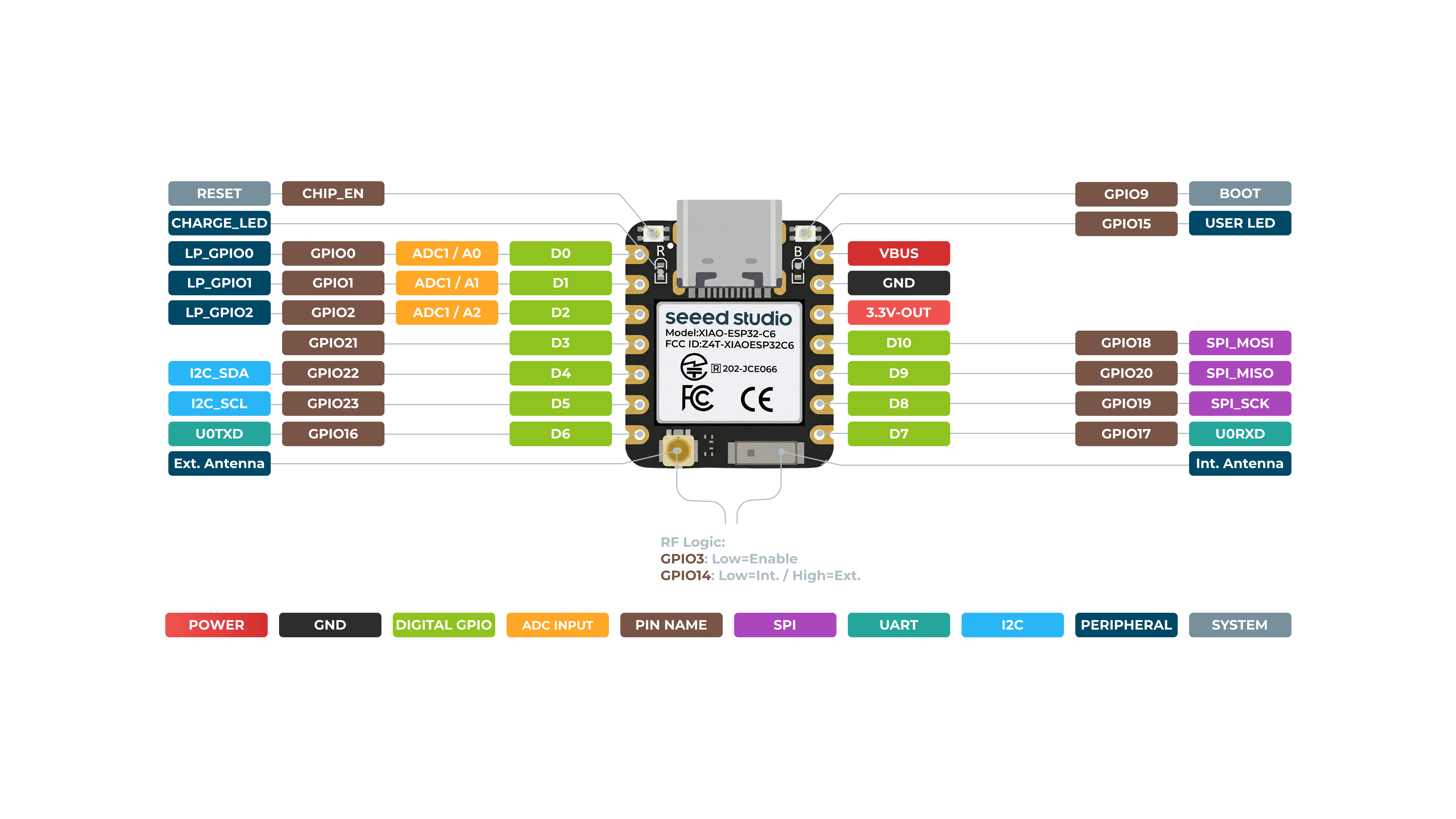
The Seeed Studio ESP32-C6 Xiao board has a reset button and a bootloader button, as well as a user LED on GPIO15. After reset, the bootloader button may be used by the application.
GPIO overview:
- 1 x UART
- 1 x LP_UART (not supported)
- 1 x I2C
- 1 x LP_I2C (not supported)
- 1 x SPI
- 11 x GPIO (only 3 PWM channels are defined by default)
- 7 x ADC (3 usable)
- 1 x SDIO (not supported)
The purpose for which a GPIO is used depends on which module or function is used first. For example, if the periph_spi module is not used, the GPIOs listed in SPI configuration can be used for other purposes.
The following table shows the default board configuration. This configuration can be overridden by application-specific configurations.
| Function | Pin | Configuration |
|---|---|---|
| BUTTON0(Boot) | GPIO9 | GPIO9 is a strapping pin |
| LED0 | GPIO15 | User LED (low active) |
| ADC/LP_GPIO | GPIO0, GPIO1, GPIO2 | ADC Channels |
| PWM_DEV(0) | GPIO0, GPIO1, GPIO2 | PWM Channels |
| I2C_DEV(0):SDA | GPIO22 | I2C Interfaces |
| I2C_DEV(0):SCL | GPIO23 | I2C Interfaces |
| SPI_DEV(0):SCK | GPIO19 | SPI Interfaces |
| SPI_DEV(0):MISO | GPIO20 | SPI Interfaces |
| SPI_DEV(0):MOSI | GPIO18 | SPI Interfaces |
| SPI_DEV(0):CS0 | GPIO21 | SPI Interfaces |
| UART_DEV(0):TxD | GPIO16 | UART interfaces |
| UART_DEV(0):RxD | GPIO17 | UART interfaces |
For detailed information about the peripheral configurations of ESP32-C6 boards, see section Common Peripherals.
RF Antenna Switch
The board has an RF switch to toggle between the built-in ceramic antenna and an external U.FL antenna. It is controlled by two GPIOs:
- GPIO3 (RF switch enable, active low) powers the switch.
- GPIO14 selects the antenna: low for the built-in ceramic antenna (default), high for the external U.FL antenna.
The built-in ceramic antenna is used by default, so no configuration is required for the common case. The board_init function configures the RF switch accordingly at startup.
To use the external U.FL antenna instead, enable the CONFIG_XIAO_ESP32C6_EXT_ANTENNA option, for example by adding the following line to the application's Makefile:
- Note
- The external antenna path has not been tested due to a missing external antenna.
Battery Usage
The XIAO ESP32C6 series features a built-in power management chip, allowing it to be powered independently by a battery or to charge the battery through its USB port.
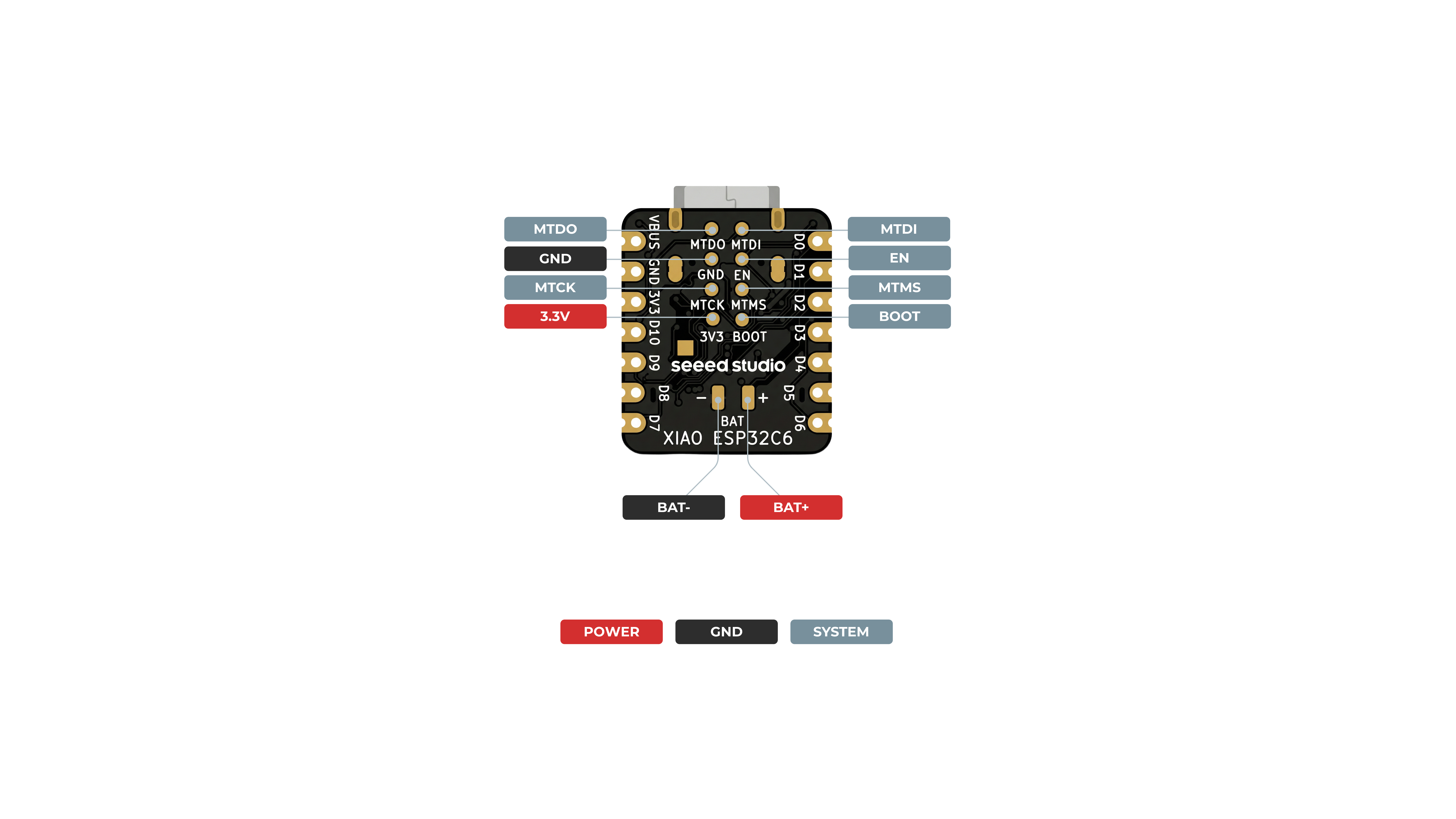
For connecting a battery to your XIAO, it's recommend using a qualified rechargeable 3.7V lithium battery. When soldering the battery, carefully distinguish between the positive and negative terminals. The negative electrode pad should be located on the left side near the silk screen marking "D8", while the positive electrode pad should be located on the right side near the silk screen marking "D5".
- Note
- When the board is powered from the battery, no voltage is present on the 5V pin.
-
The XIAO ESP32C6 has a red indicator light for battery charging, similar to the XIAO ESP32S3: The red light behavior for the XIAO ESP32C6 is as follows:
- When no battery is connected:
- The red light turns on when the Type-C cable is connected and turns off after 30 seconds.
- When a battery is connected and the Type-C cable is plugged in for charging:
- The red light flashes.
- When the battery is fully charged via the Type-C connection:
- The red light turns off.
- When no battery is connected:
To monitor the battery voltage on the XIAO ESP32C6, similar to the XIAO ESP32C3, you'll need to solder a 200k resistor in a 1:2 configuration. This setup reduces the voltage by half, allowing safe monitoring through the A0 analog port.
Sample Code can be found in The Seeed Wiki.
Deep Sleep and Wake-up
On the XIAO ESP32C6, only GPIO0, GPIO1 and GPIO2 of these RTC-capable pins are broken out and can therefore be used as wake-up sources.
Board Pinout
The following figure shows the pinout as configured by default board definition.
Board documentation
- Schematic (PDF)
- Pinout (XLSX)
- ESP32-C6 Datasheet (PDF)
- ESP32-C6 Technical Reference Manual (PDF)
- Product Page
- Wiki Page
Flashing the Device
The USB-C connector of the board is directly connected to the USB Serial/JTAG interface of the ESP32-C6 SoC. It can be used to program the board and to debug the application. Just connect the board to your host computer and use the following command:
Files | |
| file | arduino_iomap.h |
| Mapping from MCU pins to Arduino pins. | |
| file | board.h |
| Board specific definitions for the Seeed Studio XIAO ESP32-C6. | |
| file | periph_conf.h |
| Peripheral configurations for the Seeed Studio XIAO ESP32-C6. | |