Support for the STM32F4Discovery board. More...
Detailed Description
Support for the STM32F4Discovery board.
Hardware
MCU
| MCU | STM32F407VGT6 |
|---|---|
| Family | ARM Cortex-M4 |
| Vendor | ST Microelectronics |
| Package | LQFP100 |
| RAM | 192 KiB (128 KiB RAM + 64 KiB CCMRAM) |
| Flash | 1024 KiB |
| Frequency | up to 168 MHz |
| FPU | yes |
| Timers | 14 (12× 16bit, 2× 32bit [TIM2 + TIM5]) |
| ADCs | 3× 16 channel 6 to 12-bit |
| UARTs | 6 |
| SPIs | 3 |
| I2Cs | 3 |
| Vcc | 2.0 V - 3.6 V |
| MCU Datasheet | MCU Datasheet |
| Reference Manual | Reference Manual |
| Programming Manual | Programming Manual |
| Board Manual | Board Manual |
STDIO
By default, STDIO is implemented via the native USB interface.
Using USB
Connect your computer via the micro USB connector to the board. (It is safe to connect both the native USB port of the MCU at the micro USB connector and the ST-Link programmer/debugger at the mini USB connector at the same time.)
Afterwards, simply run (with the current working directory of your terminal set to directory of the app you flashed):
Using UART
Connect your USB to UART bridge as follows:
| Pin UART Adapter | Pin Board |
|---|---|
| TXD | RXD (PA3) |
| RXD | TXD (PA2) |
| GND | GND |
Now flash with stdio over UART by selecting the module stdio_uart and connect to the serial. You can do both by running in a terminal (and the working directory set to the directory of the app you want to run):
- Note
- The
USEMODULE=stdioneeds to be specified before themakecommand to pass it as environment variable.
RIOT pin mapping
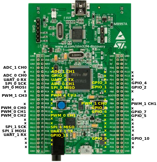
Please refer to this document for the RIOTs pin mapping for the stm32f4discovery board. The pin mapping is chosen completely arbitrary and can be altered by editing the boards/stm32f4discovery/include/periph_conf.h header file.
User Interface
2 Buttons:
| NAME | USER | RESET |
|---|---|---|
| Pin | PA0 (IN) | NRST |
6 User controllable LEDs:
| NAME | LD3 | LD4 | LD5 | LD6 | LD7 | LD8 |
|---|---|---|---|---|---|---|
| Color | orange | green | red | blue | green | red |
| Pin | PD13 | PD12 | PD14 | PD15 | PA9 | PD5 |
LEDs LD7 and LD8 are used by the USB connector for over-current (LD8) and data (LD7) indication.
USB Device Interface
The board has a micro USB port that can be used for USB device mode. As the ST-Link on the board does not provide a USB-UART interface, the STDIO is mapped to the micro USB port by default (via CDC ACM).
Accelerometer
The STM32F4discovery board contains a 3-axis MEMS accelerometer that can sample with up to 1.6kHz.
| Sensor | LIS3DSH |
|---|---|
| Type | Accelerometer |
| Vendor | ST Microelectronics |
| Datasheet | Datasheet |
Pin Config
| Pin / Bus | Function |
|---|---|
| SPI bus (RIOT) | SPI_DEV(0) |
| SPI bus (hardware) | SPI1 |
| SCK | PA5 (OUT, SPI1_SCK) |
| MISO | PA6 (IN, SPI1_MISO) |
| MOSI | PA7 (OUT, SPI1_MOSI) |
| INT1 | PE0 (IN) |
| INT2 | PE1 (IN) |
| CS | PE3 (OUT) |
Digital Microphone
The STM32F4discovery board contains a on-board MEMS audio sensor.
| Sensor | MP45DT02 |
|---|---|
| Type | Audio sensor |
| Vendor | ST Microelectronics |
| Datasheet | Datasheet |
Pin Config
| Pin / Interface | Function |
|---|---|
| I2S interface (hardware) | I2S2 |
| I2S interface (RIOT) | n/a |
| CLK | PB10 |
| DOUT | PC3 |
Audio DAC with integrated class D speaker driver
The board contains an digital analog converter (DAC) with integrated class D speaker driver.
| Device | CS43L22 |
|---|---|
| Type | DAC |
| Vendor | Cirrus Logic |
| Datasheet | Datasheet |
Pin Config
| Pin / Interface / Bus | Function |
|---|---|
| Analog (hardware) | DAC1 |
| Analog (RIOT) | DAC_LINE(0) |
| I2S interface (hardware) | I2S3 |
| I2S interface (RIOT) | n/a |
| I2C bus (hardware) | I2C1 |
| I2C bus (RIOT) | I2C_BUS(0) |
| AIN1 | PA4 (DAC1_OUT) |
| SCL | PB6 (I2C1_SCL) |
| SDA | PB9 (I2C1_SDA) |
| MCLK | PC7 (I2S3_MCK) |
| SCLK | PC10 (I2S3_CK) |
| SDIN | PC12 (I2S3_SD) |
| RESET | PD4 (OUT) |
Flashing the Board
A detailed description about the flashing process can be found on the guides page. The board name for the STM32F4 Discovery is stm32f4discovery.
Emulator
To emulate this board you need an updated version of renode installed, at least version 1.11.
Note that stdio_cdc_acm is the default, as the integrated ST-Link does not expose the UART interface unlike modern discovery or Nucleo boards do. Since renode as of October 2026 (1.17.0) does not have a USB model, a firmware built without selecting stdio_uart will not have an stdio available in renode.
Known Issues / Problems
I2C
When connecting an I2C device and a logic analyzer to an I2C port at the same time, the internal pull-up resistors are not sufficient for stable bus operation. You probably have to connect external pull-ups to both bus lines. 10K is a good value to start with.
macOS & make term
If you want the terminal to work using make term command and get a message about missing tty device install the driver from https://www.silabs.com/products/development-tools/software/usb-to-uart-bridge-vcp-drivers
Files | |
| file | arduino_iomap.h |
| Mapping from MCU pins to Arduino pins. | |
| file | board.h |
| Board specific definitions for the STM32F4Discovery evaluation board. | |
| file | gpio_params.h |
| Board specific configuration of direct mapped GPIOs. | |
| file | periph_conf.h |