Support for the MSB-IoT board. More...
Detailed Description
Support for the MSB-IoT board.
Overview
The MSB-IoT was developed at FU Berlin and is based on a STM32F415RG MCU.
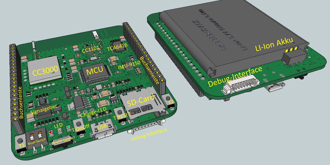
Hardware
MCU
The centerpiece of the MSB-IoT is the STM32F415RG MCU. With a maximum frequency of 168 MHz it offers high performance for a microcontroller of its category. The STM32F415RG comes with a huge set of accessible communication interfaces and features that are listed here.
| MCU | STM32F415RG |
|---|---|
| Family | ARM Cortex-M4 |
| Vendor | ST Microelectronics |
| RAM | 192KiB (128KiB RAM + 64KiB CCMRAM) |
| Flash | 1024KiB |
| Frequency | up to 168MHz |
| FPU | yes |
| Timers | 14 (12x 16bit, 2x 32bit [TIM2 + TIM5]) |
| ADCs | 3x 12-bit (16 channel) |
| UARTs | 6 (4 USART, 2 UART) |
| SPIs | 3 |
| I2Cs | 3 |
| Vcc | 1.8V - 3.6V |
| Datasheet | Datasheet |
| Reference Manual | Reference Manual |
| Programming Manual | Programming Manual |
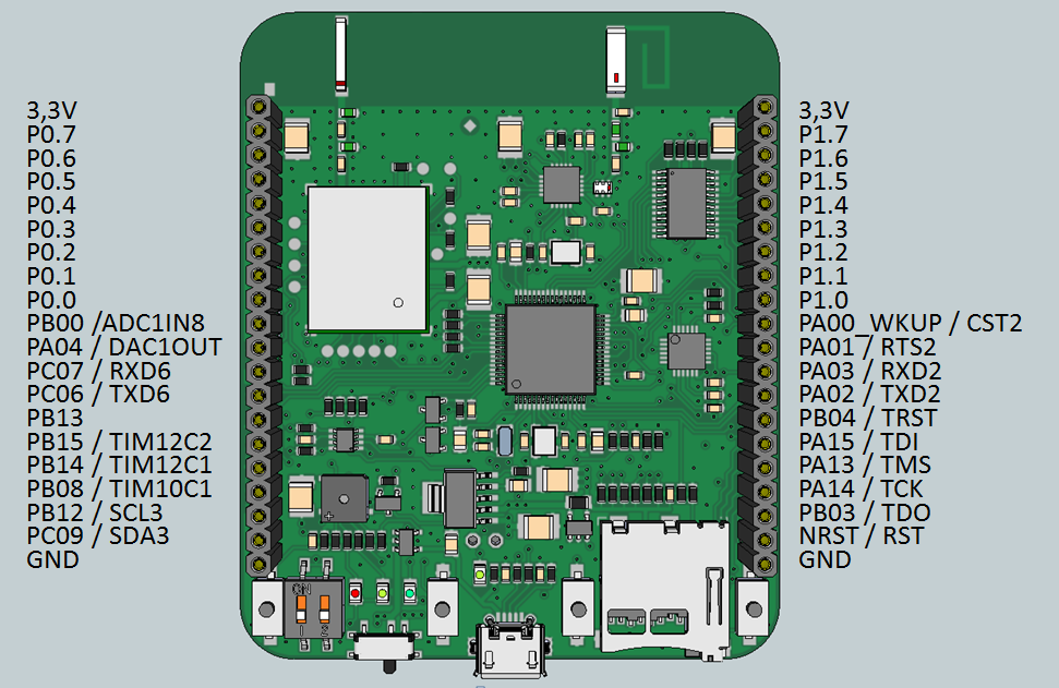
GPIO Pins
The following picture shows the easily accessible pins of the board:
User Interface
3 Buttons
| NAME | User Button T1 | User Button T2 | T RESET |
|---|---|---|---|
| Pin | PB13 | PA0 | NRST |
The user buttons are mapped to GPIO_0 (Button T2) and GPIO_8 (Button T1) in the board's default configuration file for RIOT. To configure and use the buttons, you can use RIOT's GPIO.
Pushing the reset button will always reset the board and restart your application.
3 user controllable LEDs
| NAME | LED_RED | LED_YELLOW | LED_GREEN |
|---|---|---|---|
| Color | red | yellow | green |
| Pin | PB8 | PB14 | PB15 |
| Pin Alias | LED0_PIN | LED1_PIN | LED2_PIN |
| Macros | LED0_ON, ... | LED1_ON, ... | LED2_ON, ... |
The LEDs can be controlled inside your RIOT application by using the LED macros LED0_ON, LED0_OFF, and LED0_TOGGLE for the red LED, LED1_ON, LED1_OFF, and LED1_TOGGLE for the yellow LED, and LED2_ON, LED2_OFF, and LED2_TOGGLE for the green LED. See our API documentation for more information about the standard LED macros.
There is also a yellow charge LED on the board indicating the charging process of the battery.
1 Beeper
| NAME | Beeper |
|---|---|
| Pin | PB09 |
The board's beeper allows for acoustic feedback. It needs a PWM signal between 1-5 kHz and is connected to pin PB9 and mapped to PWM_0 in RIOT. To configure and use the beeper inside your application, you can use RIOT's PWM.
CC1101 Sub-1GHz RF Transceiver
The board has an integrated CC1101 Sub-1GHz RF Transceiver which is connected to the MCU using the SPI. The transceiver allows for energy-efficient local communication in the frequency band below 1 GHz. The driver for the CC1101 automatically loaded when the pseudo module netdev_default is used.
| Product | CC1101 |
|---|---|
| Type | Sub-1GHz RF Transceiver |
| Vendor | Texas Instruments |
| Datasheet | Datasheet |
| Errata Sheet | Errata Sheet |
| Other Technical Documents | TI Webpage |
| Driver | CC1100/CC1100e/CC1101 Sub-GHz transceiver driver |
| SPI Device | SPI1 (Mapped to SPI_0 in RIOT) |
| SCL | PA5 |
| MISO | PA6 |
| MOSI | PA7 |
| CS | PB12 |
| GDO0 | PC4 |
| GDO2 | PC5 |
CC3000 802.11b/g Wi-Fi Module
In addition to the CC1101, the MSB-IoT also features a CC3000 Wi-Fi Module. The CC3000 is a self-contained wireless network module with a full embedded IPv4 TCP/IP stack that for example allows to use the MSB-IoT as a gateway node to the internet. Please note that the CC3000 only supports operation in infrastructure mode and therefore always needs to be connected to an access point to be used for communication.
The CC3000's driver implementation for RIOT includes the full driver provided by Texas Instruments. The API documentation from TI can be found here. To use the CC3000 in RIOT, just add USEMODULE += cc3000 to your application's Makefile.
The driver for the CC3000 is not yet merged into RIOT's master branch. Please see pull request #2603 for progress on the inclusion.
| Product | CC3000 |
|---|---|
| Type | 802.11b/g Wi-Fi Module |
| Vendor | Texas Instruments |
| Datasheet | Datasheet |
| Errata Sheet | Errata Sheet |
| Other Technical Documents | TI Webpage |
| TI Support Forum | WiFi Forum |
| Driver | Pull Request |
| SPI Device | SPI2 (Mapped to SPI_1 in RIOT) |
| SCL | PB10 |
| MISO | PC2 |
| MOSI | PC3 |
| CS | PC1 |
| WLAN_ENABLE | PC13 |
| IRQ Line | PA10 |
MPU-9150 Nine-Axis MotionTracking Device
The MSB-IoT is equipped with a MPU-9150 MotionTracking Device from Invensense. The device combines a gyroscope, a magnetometer and an accelerometer in one module.
Due to licensing issues, the current MPU-9150 driver implementation for RIOT is not based on Invensense's 'Motion Driver' library and offers only a limited set of features. Nonetheless, the RIOT driver allows to configure and read values from all three sensors of the device. For an overview on the supported features, you can check the driver's documentation in MPU-9X50 (MPU9150 and MPU9250) accelerometer/magnetometer/gyroscope.
A sample RIOT application for the MPU-9150 that utilizes the driver can be found here.
| Product | MPU-9150 |
|---|---|
| Type | Nine-Axis MotionTracking Device (Gyro, Accel and Compass) |
| Vendor | Invensense |
| Product Specification | Product Specification |
| Register Map | Register Map |
| Driver | MPU-9X50 (MPU9150 and MPU9250) accelerometer/magnetometer/gyroscope |
| I²C Device | I2C1 (Mapped to I2C_0 in RIOT) |
| SCL | PB6 |
| SDA | PB7 |
| IRQ Line | PB11 |
Other components
For the following components of the MSB-IoT, there is currently no support in RIOT:
- TCA6416 16-Bit I/O Expander
- Micro-SD-Card Interface
Compiling, Flashing and Debugging
This section only covers the automated functionality provided by RIOT's makefile system. If you don't want to rely on RIOT's make targets for flashing or debugging (for instance to use a different flashing tool), please check the documentation of your used tools.
Flashing
RIOT's provided functionality for debugging and flashing the MSB-IoT is based on the Open On-Chip Debugger tool. A guide with installation instructions and some other information can be found here.
You can flash the board by calling the following command:
Using RTT as STDIO
By default stdio_rtt is used. So just connect the ST-Link and type BOARD=msbiot make term and you'll get the serial console.
Using the UART for STDIO
The MCU's USART2 that is routed to the pin headers is mapped as UART_0 and the default UART for when stdio_uart is used. Since stdio_rtt is the default you need to use
Note that you need to rebuild and flash the app when switching the stdio backend.
Connect your adapter and the boards pin strip with RX<=>PA02, TX<=>PA03 and GND<=>GND
Files | |
| file | board.h |
| Board specific definitions for the MSB-IoT board. | |
| file | gpio_params.h |
| Board specific configuration of direct mapped GPIOs. | |
| file | periph_conf.h |