Support for the ESP32 ProS3 board. More...
Detailed Description
Support for the ESP32 ProS3 board.
ESP32 ProS3
Overview
The ESP32 ProS3 is one of the ESP32-S3 boards from Unexpected Maker. 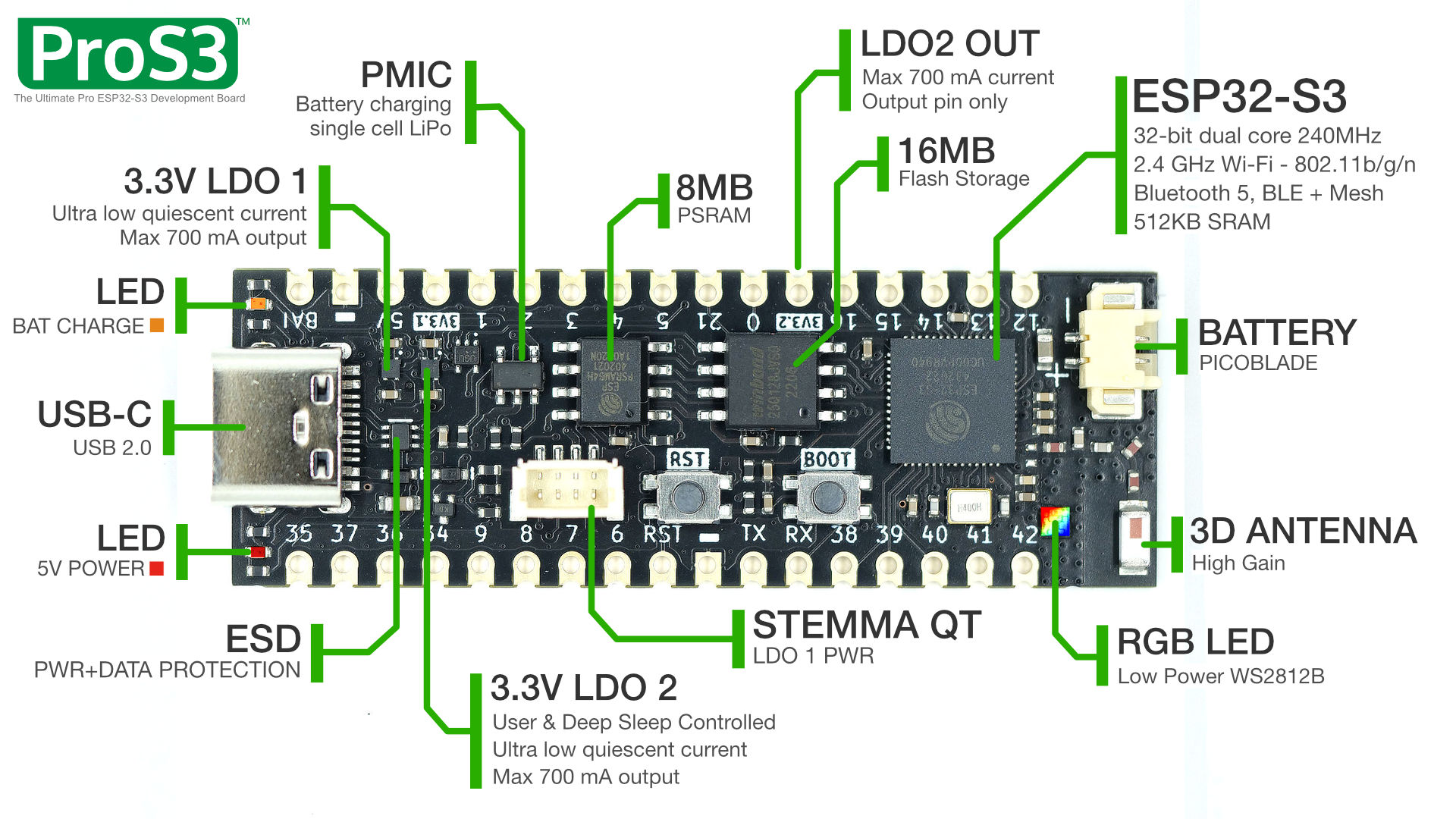
The main features of the board are:
- ESP32-S3 SoC with 2.4 GHz WiFi 802.11b/g/n and Bluetooth5, BLE
- 16 MByte Flash
- 8 MByte QSPI RAM
- RGB LED WS2812B
- Native USB and USB Serial JTAG
- LiPo Battery Charging and PicoBlade connector
- VBAT and 5V Sensing Pins
- 3D High Gain Antenna
Hardware
MCU
Most features of the board are provided by the ESP32-S3 SoC. For detailed information about the ESP32-S3 SoC variant (family) and ESP32x SoCs, see section ESP32 SoC Series.
Board Configuration
ESP32 ProS3 boards have no special hardware on board with the exception of a single pin RGB-LED WS2812B that uses a special bit-oriented protocol to control the RGB-LED by 24-bit RGB values which is not supported yet.
Most GPIOs are broken out on the board for flexibility. The default board configuration provides:
- 10 x ADC channels at maximum
- 1 x SPI
- 1 x I2C
- 1 x UART
- 2 x PWM, 4 channels each
- 1 x RGB-LED
For flexibility, some GPIOs are used in different peripheral configurations, but they can only be used for one peripheral at a time. For example, GPIO9 is used in the ADC channel definition and the definition of the SCL signal for I2C_DEV(0).
This is possible because GPIOs are only used for a specific peripheral interface when either
- the corresponding peripheral module is used, e.g.
periph_i2c, or - the corresponding init function is called, e.g.
adc_init.
That is, the purpose for which a GPIO is used depends on which module or function is used first.
For example, if module periph_i2c is not used, the GPIOs listed in I2C configuration can be used for the other purposes, that is, GPIO9 can be used as ADC channel.
The following table shows the default board configuration, which is sorted according to the defined functionality of GPIOs. This configuration can be overridden by application-specific configurations.
| Function | GPIOs | Remarks | Configuration |
|---|---|---|---|
| BTN0 | GPIO0 | labeled as BOOT button | |
| ADC_LINE(n) | GPIO1, GPIO2, GPIO3, GPIO4, GPIO5, GPIO6, GPIO7, GPIO8, GPIO9, GPIO10 | ADC Channels | |
| PWM_DEV(0) | GPIO12, GPIO13, GPIO14, GPIO15, GPIO16 | - | PWM Channels |
| PWM_DEV(1) | GPIO6, GPIO7, GPIO21, GPIO38 | - | PWM Channels |
| I2C_DEV(0) SCL | GPIO9 | I2C Interfaces | |
| I2C_DEV(0) SDA | GPIO8 | I2C Interfaces | |
| SPI_DEV(0) CLK | GPIO36 | SPI2_HOST (FSPI) is used | SPI Interfaces |
| SPI_DEV(0) MISO | GPIO37 | SPI2_HOST (FSPI) is used | SPI Interfaces |
| SPI_DEV(0) MOSI | GPIO35 | SPI2_HOST (FSPI) is used | SPI Interfaces |
| SPI_DEV(0) CS0 | GPIO34 | SPI2_HOST (FSPI) is used | SPI Interfaces |
| UART_DEV(0) TxD | GPIO43 | Console (configuration is fixed) | UART interfaces |
| UART_DEV(0) RxD | GPIO44 | Console (configuration is fixed) | UART interfaces |
For detailed information about the peripheral configurations of ESP32-S3 boards, see section Common Peripherals.
Board Pinout
The following figure shows the pinout as configured by board definition.
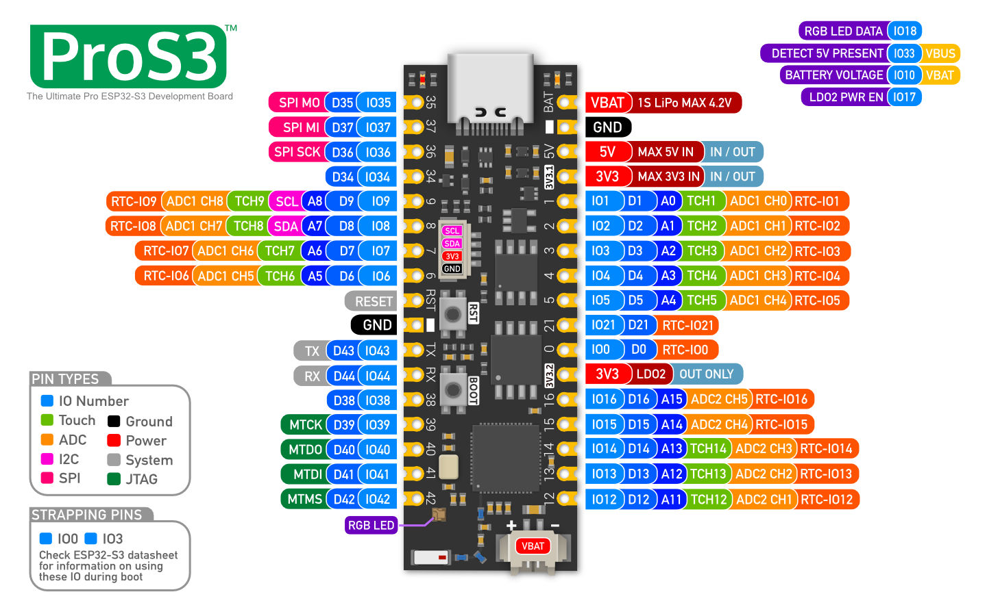
The corresponding board schematic can be found here
Flashing the Device
Since the board does not have a USB-to-Serial chip, the easiest way to flash the board is using the USB Serial/JTAG interface. Just connect the board to your host computer and use the following command:
- Note
- Usually the make system resets the board before flashing to enable the USB Serial/JTAG interface. In some special cases this reset does not work so that the programmer cannot connect to the board and the flashing is aborted with a timeout:
This can happen for example if the board is not yet flashed with RIOT or the USB interface is used for another purpose. In this case, restart the board manually in download mode by pressing and releasing the RESET button while holding down the BOOT button. In download mode, the USB Serial/JTAG interface is always available.
Alternatively, an external USB-to-Serial adapter can be used. In this case, the USB-to-Serial adapter has to be connected to TxD (GPIO43) and RxD (GPIO44) of the UART0 interface. Before RIOT can be flashed, the board has to be switched to download mode. To do this, press and release the RESET button while holding down the BOOT button. Once the board is in download mode, use the following command to flash RIOT:
For detailed information about ESP32-S3 as well as configuring and compiling RIOT for ESP32-S3 boards, see RIOT-OS on ESP32 SoC Series Boards.
Using STDIO
Since the board does not have a USB-to-Serial chip, the USB Serial/JTAG interface is used by default for the STDIO (module stdio_usb_serial_jtag) which provides an USB CDC ACM interface.
If the USB port is used by the USBUS stack or the tinyUSB stack, implicitly the module stdio_cdc_acm or stdio_tinyusb_cdc_acm is used for the STDIO via the USB CDC ACM interface.
Alternatively, the UART interface could be used with an external USB-to-Serial adapter. Simply add stdio_uart to the list of used modules for this purpose:
Files | |
| file | arduino_iomap.h |
| Mapping from MCU pins to Arduino pins. | |
| file | board.h |
| Board definitions for ESP32 ProS3 boards. | |
| file | gpio_params.h |
| Board specific configuration of direct mapped GPIOs. | |
| file | periph_conf.h |
| Peripheral configurations for ESP32 ProS3 boards. | |
